Net and Gate Delays in Verilog
Types of Gate Delays
Till now we have only discussed zero-delay scenarios i.e. the output was immediate to the change in inputs. In real circuits logic gates have delays associated with them.
Rise Delay and Fall Delay
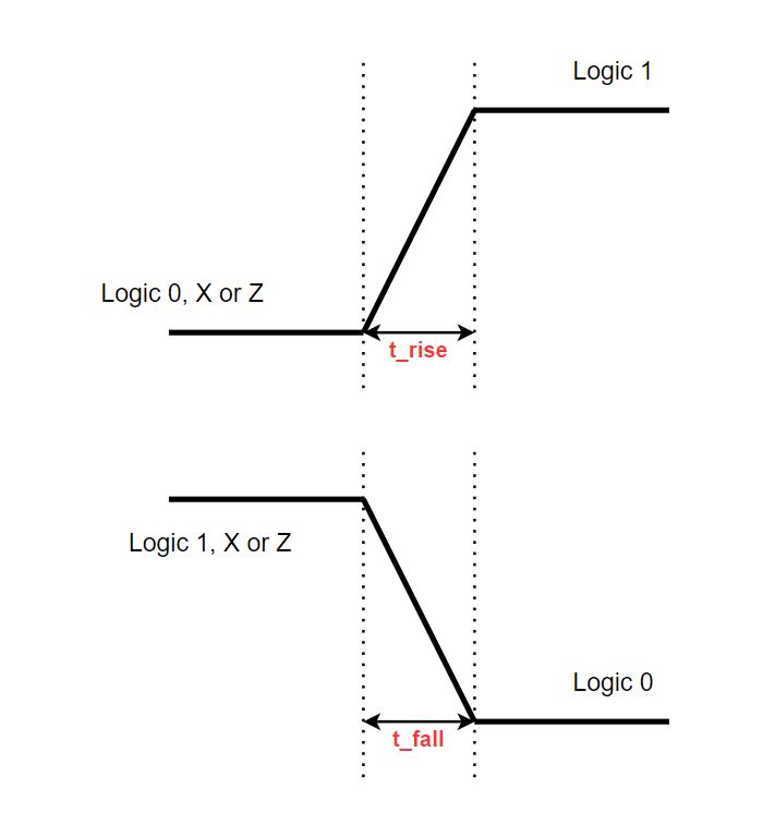
The Rise Delay or Rise Time is associated with a gate output transition to a 1 from another state.
The Fall Delay or Fall Time is associated with a gate output transition to a 0 from another state.
Diagram below represents the Rise Delay and Fall Delay of a signal.
Turn-Off Delay
The Turn-Off Delay is associated with a gate output transition to the High Impedance state (Z) from another value.
Gate Delays vs Net Delays
Gate Delays allow the verilog user to specify delays through the logic circuits.
Gate and Net Delays provide a means of more accurately describing delays through a circuit.
The Gate Delays specify the signal propagation delay from any gate input to the gate output. Up to three values per output representing Rise, Fall, and Turn-Off delays can be specified
Net Delays refer to the time it takes from any driver on the net changing value to the time when the net value is updated and propagated further. Up to three delay values per net can be specified.
Rules of specifying delays (For both Gates and Nets) :- For both gates and nets, the 'default delay' shall be zero when no delay specification is given.
- When one delay value is given, then this value shall be used for all propagation delays associated with the gate or the net.
- When two delays are given, the first delay shall specify the rise delay, and the second delay shall specify the fall delay. The Turn-Off delay is the minimum of the two delays.
- For a three delay specification, The first corresponds to the 'Rise Delay', the second corresponds to the 'Fall Delay' and the third to the 'Turn-Off' delay.
Refer below example code for the different type of delay specifications :
Minimum / Typical / Maximum (Min/Typ/Max) Delays
Verilog provides an additional level of control for each type of delay (Rise, Fall and Turn-Off) mentioned before.
For each type of delay (Rise, Fall and Turn-Off), three values min, typ and max can be specified.
Any one value can be chosen at the start of the simulation.
Min/Typ/Max values are used to model devices whose delays vary within a minimum and maximum range because if IC Fabrication process variations.
Minimum Value (Min) : Minumum delay value that the designer expects the gate to have.
Typical Value (Typ) : Typical delay value that the designer expects the gate to have.
Maximum Value (Max) : Maximum delay value that the designer expects the gate to have.
Min, Typ, Max values can be closed at verilog runtime
Refer below example code for the different types of Min/Typ/Max delay specifications :